CAPACITIVE AND CIRCULATING CURRENTS IN ELECTRIC MOTORS


Better Understanding of These Harmful Effects


Nearly three decades ago while working at a pulp and paper mill in Oregon, Hugh Boyanton was tasked with the job of determining why a paper mill rebuild was plagued with a new onset of motor bearing damage. His pioneering work led to the identification of a new class of bearing damage known as electrically induced motor bearing damage due to capacitive discharge between the motor shaft and the bearing. This new class of bearing damage was the direct result of using a new technology known as variable frequency drives. To learn more about this specific endeavor, please visit the following link to read his detailed article:

https://www.shaftgroundingsystems.com/yahoo_site_admin/assets/docs/Technical_Document_Updated_2020.36143829.pdf


This article discusses the differences between bearing damage caused by capacitive discharge and circulating currents. At the time of the above referenced paper mill study, circulating currents were not appreciated as being a potential reason for electrically induced bearing damage. Even today, best practices for eliminating electrically induced bearing damage due to circulating currents are often overlooked by those in charge of commissioning motors or even downstream maintenance crews. The following will help decision makers better understand the different classes of electrically induced bearing damage and best practice recommendations.


Capacitive Discharge


Capacitive currents result from the use of gated devices such as a silicon controlled rectifier (SCR), insulated-gate bipolar transistor (IGBT) or gate turn-off transistor (GTO). The gated device of an SCR turns on depending on the primary voltage of the drive. The turn-on time going from zero volts to as high as 650 volts will occur in microseconds. This rapid voltage change causes a difference of potential between the rotor and the non-rotating parts of the motor. When the potential increases to a level of 3 or 4 volts the dielectric ability of the bearing oil is compromised and current arcs across the bearing races to the balls. When the arc occurs, it burns a small amount of metal out of the bearing races and balls. This process is most like electric discharge machining (EDM) a common manufacturing process for shaping metal. For SCRs, EDM only occurs when the SCR turns on as the SCR shuts off when the voltage goes past zero. Shaft-to-frame voltages are quite high in an SCR set-up, however, EDM will only occur a maximum of 360 times per second.


In the case of other gated devices, they can be turned on and off 2,000 to 20,000 times per second. Every time the gated device is turned on or off a shaft-to-frame potential is created that can exceed the breakdown voltage of the oil in the bearing lubricant (dielectric) that will lead to EDM.


Electric discharge machining in an SCR can only happen when the gate is turned on. This is not the case with other devices where EDM will occur when the gated device is on or off. Non-SCR gated devices do not experience as high a voltage potential as SCRs, but they still exceed the 3 to 4 volt threshold discussed earlier and the shaft-to-frame potentials occur far more often than SCR devices. The reason why non-SCR devices do not experience as high a voltage potential is as follows:


  1. In the case of SCRs the major voltage applied to the rotor can be as high as 500 volts and the field coils are normally not that high.
  2. In an AC motor the voltage on the rotor is normally less than 100 volts. The stator has full line voltage.
  3. The voltage spikes occur every time the gated device turns on or off. The shaft-to-frame voltage is lower, but at times it exceeds the break over voltage of the lubricant (dielectric). This occurs thousands of times more per second than the SCR device. Although DC motor shaft voltage spikes are much higher than AC motor voltage spikes, the smaller AC voltage spikes occur at a much higher frequency and lead to electrically induced motor bearing damage just the same.

The following is the test arrangement used for testing shaft-to-frame potential and current flow:


Circulating Currents in Motors


Circulating currents are a less understood phenomenon than capacitive discharge. It has only been relatively recently that the field has realized electrically induced bearing damage can be the result of circulating currents rather than just capacitive coupling. Companies, such as semiconductor plants, are now starting to specify their motors with counter measures to combat circulating currents.


Shaft Grounding Systems, Inc. has confirmed via field testing in a number of installations in the United States and Europe that motors over 100hp at speeds under 1800rpm can have circulating currents present. In addition, motors above 200hp and regardless of rpm will be at increased risk for these currents.


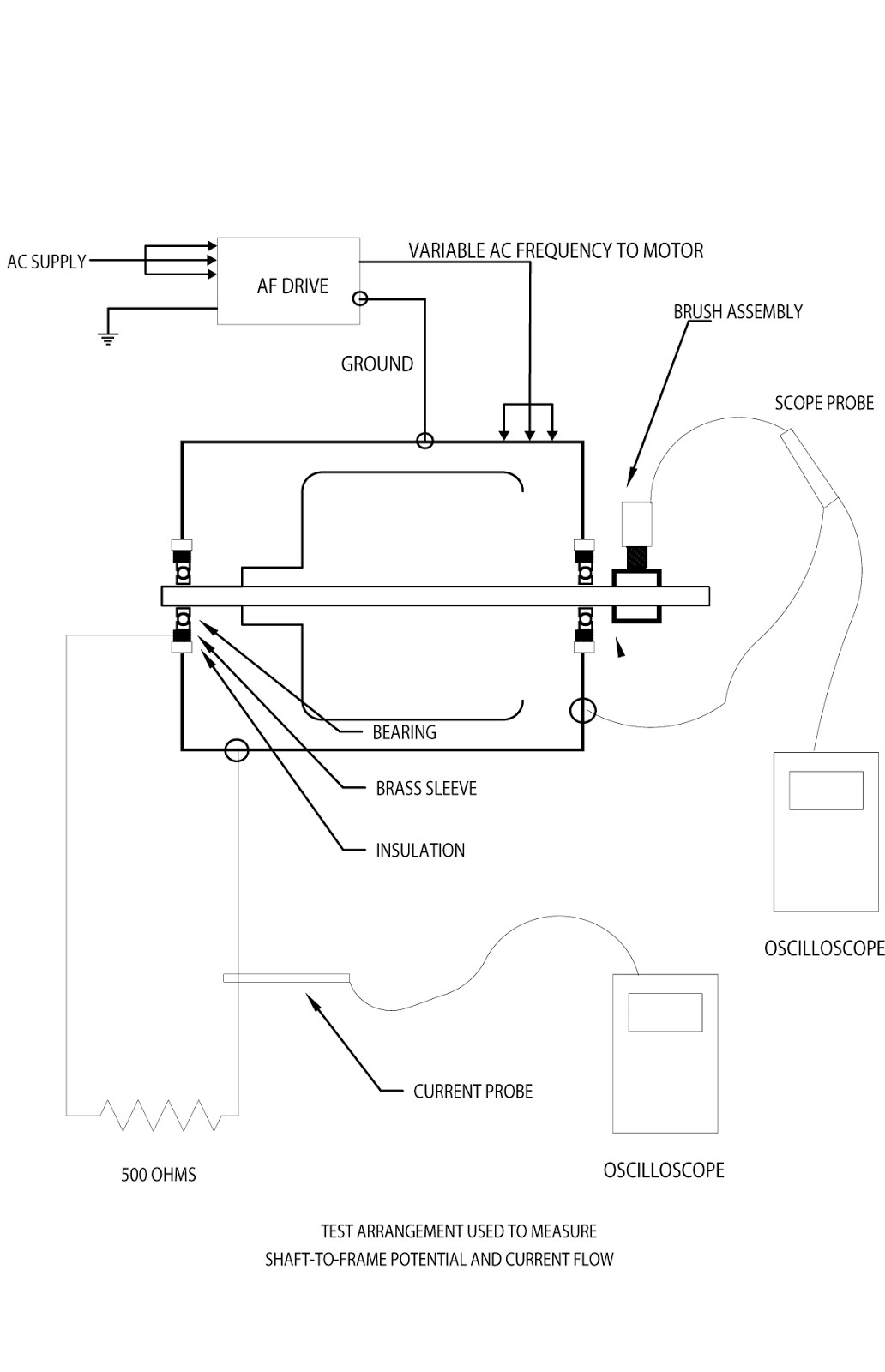
One installation in particular had the ability to run their motors on the AC drive or across the line using a bypass switch. While running off the drive with an SGSTM drive end shaft grounding system installed, shaft voltage measurements were obtained on the outboard end of the motor. Of note, the motor did not have insulated bearings. Insulating the installed SGSTM shaft grounding system, the motor was restarted across the line. Shaft-to-frame voltages were obtained from both ends of the motor despite the AC drive being eliminated from the equation. Installing a shaft grounding device on both ends of the motor corrected the problem.


In short, capacitive coupling was not the issue in this case but rather circulating currents as measured when the motor was powered across the line. Without insulated bearings, the only practical method of eliminating circulating currents is to provide shaft grounding on both ends of the motor. Grounding only one end of the motor will protect that particular bearing, but circulating currents will find an alternative parallel pathway and take out the other motor bearing and/or downstream connected equipment.


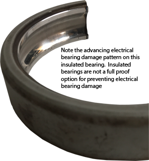
Currently, Shaft Grounding Systems, Inc. and DP&A Sales do not recommend using insulated bearings. Our 30 years of field experience has seen many insulated bearings succumb to electrically induced bearing failure. We have many customers that have realized insulated bearings are not a fail-safe option for preventing electrically induced bearing damage and will use SGSTM shaft grounding systems as a back-up for if insulated bearings fail. In addition, insulated bearings do not effectively address circulating currents.


Circulating currents are becoming a more recognized issue in the field and further research is needed to determine their exact cause. That said, Shaft Grounding Systems, Inc. has studied this phenomenon for three decades and has the following observations and suggestions for why circulating current occur. Problems associated with motor manufacturing. For example, motors will not have the exact length of magnet wire in each phase. Air pockets can form in the rotor when the molten aluminum is poured. Broken or cracked rotor bars. Magnetized motor shafts Not only do motor manufacturing defects or incidental motor damage appear to cause circulating currents, but certain industrial processes can induce these types of currents. For example, non-metallic pump housings pumping saltwater have been seen to cause electrical currents in bearings, pumps and motors such as those found in aquariums, deep water well pumps and nuclear power plants pumping saltwater for their heat exchangers. Shaft Grounding Systems, Inc. has also been involved with the US Navy assessing and mitigating shaft currents on nuclear submarines caused by the propeller turning in saltwater. If you have any questions regarding when to be concerned about circulating currents and how to mitigate their harmful effects, then give us a call and we can discuss your particular application.